Designing autonomy for combat robots at NHRL - May 2026
Project link
github.com/Woz4tetra/auto-battlebot
Our robots
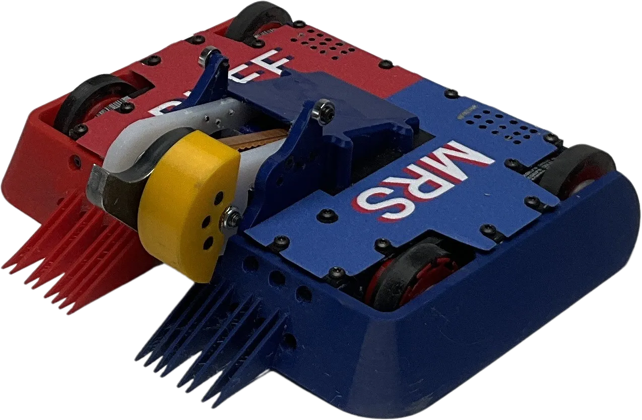
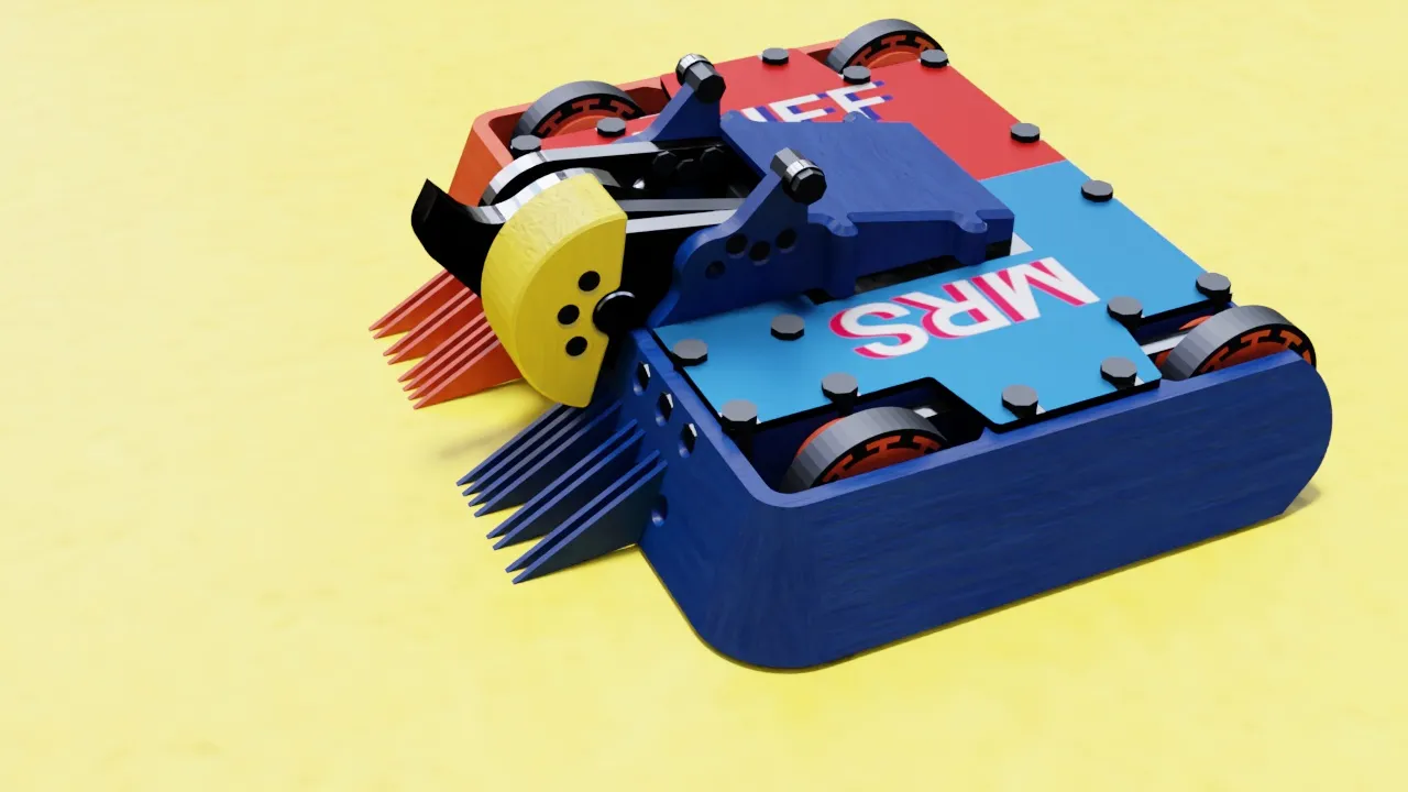
Mrs Buff MK3. Competed at NHRL in May 2026
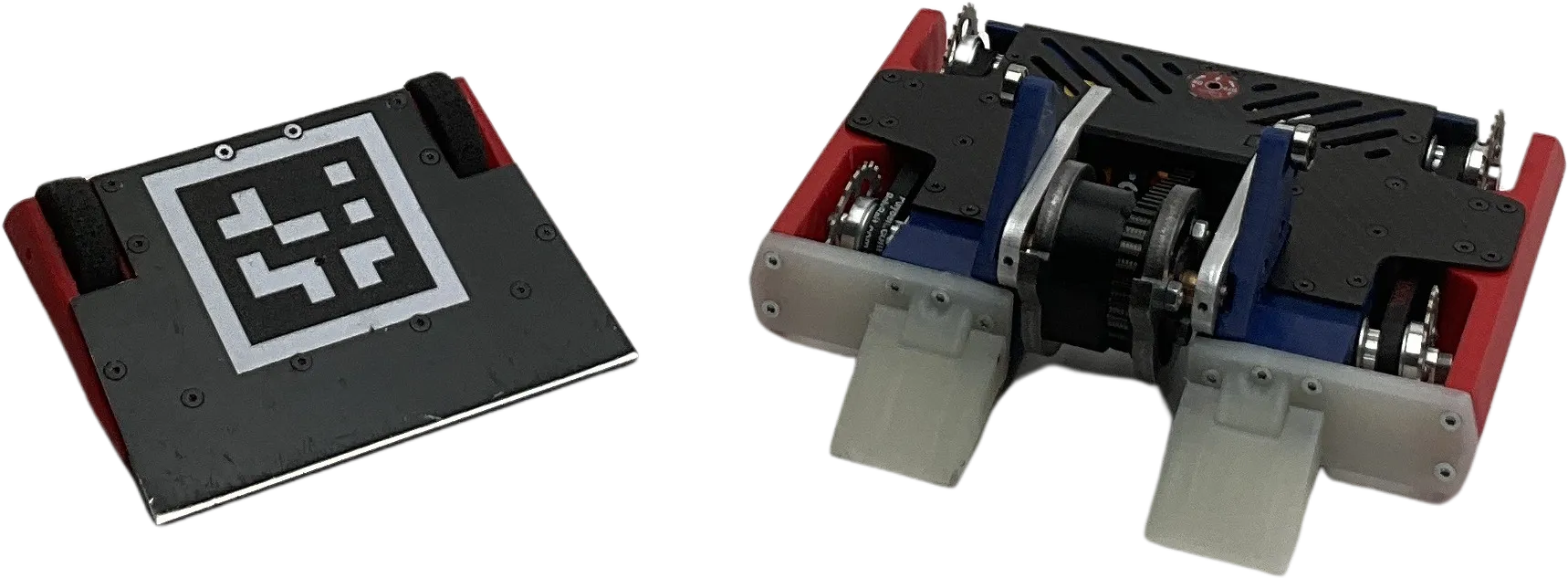
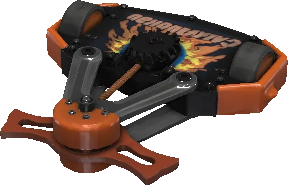
Mrs Buff MK2 and Mrs Stabs MK2. Competed at NHRL in October 2024
Overview
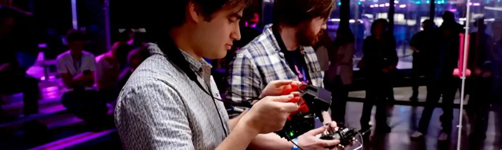
Aidan and I compete in a combat robotics competition called NHRL. Find out more here. Robots fight until they can’t move anymore or 3 minutes elapse. Judges score fights that go to time. We participate in the 3 lb league.
This article covers work from December 2025 to May 2026.
Our objectives for May 2026:
- Make 1 robot that kicks ass (as opposed to focusing on multi-bot)
- Don’t change the form factor drastically
- Augment Aidan’s driving with autonomy
- Participate in the May 2026 event
How it went:
- Aidan designed and built 1 robot. It ranked 9th and got knocked out one round before quarterfinals. In our past
attempts, we lost the first qualifying round or got knocked out before then.
- The weapon blade was changed from a drisk (hybrid drum disk weapon) to a single disk. The titanium cleats were swapped for cast urethane. The wheel guards were pushed as low to the ground as possible for better ground clearance. However, the attack strategy and driving layout remained the same.
- For matches where we were right side up or not waiting for an unstick, autonomy was active 80% of the time.
- Aidan said he was relying on it for aiming and only nudged it to do the right thing when appropriate.
- We got melted in on of our fights. More on that later.
- We made it to the event as planned. We weren’t sure if we’d go early or later for a while but we locked in mid-March.
There were many engineering advancements made to accomplish this. I will be focusing on the software/autonomy component.
What we had already
github.com/Woz4tetra/true_battlebot contains a ROS 1 + docker implementation of this project used in prior events. It showed promise but was failing to meet latency requirements and I felt its structure was interfering with development.
I’ve moved on from this repository for several reasons:
- Maintaining the docker images was time consuming.
- I upgraded Nvidia drivers on my machines and it broke the containers
- Testing and debugging the container would take hours since some steps had to redownload and install gigabytes of Nvidia dependencies
- ROS 1 is obsolete. I had to maintain two versions of python in two docker containers. Backwards compatibility was becoming a problem.
- Performance. This repo used ROS 1. The parallelized architecture made it difficult to characterize latency. The selected trajectory planner was insufficient to control the robot. Python is slow.
- Our old wedge bot, Mr Stabs MK2, had poor driving abilities because of its construction.
Our last event showed several issues with the design as well that needed changing:
- The YOLO keypoints model was noisy and unreliable. I had to filter the output to make up for its lack of performance.
- Tracking opponents was unreliable. The model wouldn’t detect opponents sometimes. The dataset wasn’t big enough to cover new robots.
- Relying on a microcontroller in between the receiver and the motor ESCs is unreliable.
- The motors would lock up sometimes after a hit. Our theory is the reset button was being pressed after an impact with a weapon.
- Setup time at the cage is critical. NHRL staff are nice but towards the end of the day, they don’t wait for you to finish setting up.
- NHRL changed the rules to make mini-bots a disadvantage, so we needed to move the autonomy to the main bot.
- Hand labeling images was time consuming. It took 6 months to label 5000 images. I needed to do this every time we updated the design.
How we addressed these issues
| Problem | Solution |
|---|---|
| Maintaining docker was time consuming | Created a new repository. A fresh start. No docker containers. Target 2 architectures on 2 machines. |
| ROS 1 is obsolete | Use ROS 1 for Foxglove integration only. It can be easily replaced with another protocol. |
| Performance | Only C++ running during a fight. One thread for perception and control. |
| Mr Stabs MK2 had poor driving | Tune driving on Mrs Buff MK3 |
| YOLO keypoints model was noisy | Synthetic data generation |
| Tracking opponents was unreliable | Label propagation with SAM3 and synthetic data generation |
| Microcontroller is unreliable | No sensors or feedback on Mrs Buff MK3 |
| Setup time at the cage | Develop a hand-held, compute device |
| Mini-bots are a disadvantage | Focus on Mrs Buff MK3 |
| Slow hand labeling | Synthetic image generation and video propagation |
Our approach
I decided early in the project that any sensors on the robot will be unreliable. I made one exception for an IMU where its only function is to reverse forward/backward commands when upside down. Anything you put in the cage you must assume will be destroyed. Encoders are usually delicate disks, cameras have fragile cables and lenses.
I also decided not to have any heavy compute onboard. This is for cost and weight reasons. A raspberry pi 4 weighs 50 g. Doesn’t sound like a lot but adding armor around the board quickly adds to the weight. The motors used on Mrs Buff MK3 were 44.5 g. Adding compute takes precious weight away from motors and weapon.
Given all this, I designed the compute and sensing to live outside the cage where there are no weight restrictions. This does pose a challenge though. How do you know which blob of pixels is you vs. your opponent vs. the background?
Keypoints model
Machine vision is equipped to solve this problem. I selected yolo26n-pose for this design. It runs in 10 ms with TensorRT on the Jetson Orin Nano. The output is the location of the front and back points on the robot. This gives me position and orientation.
However, this isn’t a complete solution. The keypoints are on a 2D image. I need the robot’s position in 3D space. Luckily, combat robots operate on a plane. With the exception of Spitfire, if the robot is in the air, it’s not controllable. If I can project the 2D keypoints onto a 3D plane, I will know the robot’s position in space. I’m using the StereoLabs ZED 2i camera. Their API provides the camera lens intrinsics matrix. Using this matrix, I can convert the pixel coordinates of the keypoints to 3D rays cast from the camera’s pinhole. The intersection of that ray with the plane of the cage floor is where my robot is located.
flowchart TB
    A(Left camera image) -->|rgb image| B(YOLO pose)
    B -->|keypoints| C(Camera intrinsic matrix)
    C -->|3D rays| D(Compute ray-plane intersection)
    D -->|3D points| E(Compute rotation and offset between two vectors)
    E --> F(Robot pose)
Floor model
But how do I get the 3D plane of the cage floor? In the code I call this the “field”. The first problem is locating the field edges. I’m using a semantic segmentation model called DeepLabV3Plus. It labels every pixel in an image as “field” or “background”. I’ve found it to be robust to new camera angles. Here’s an example:
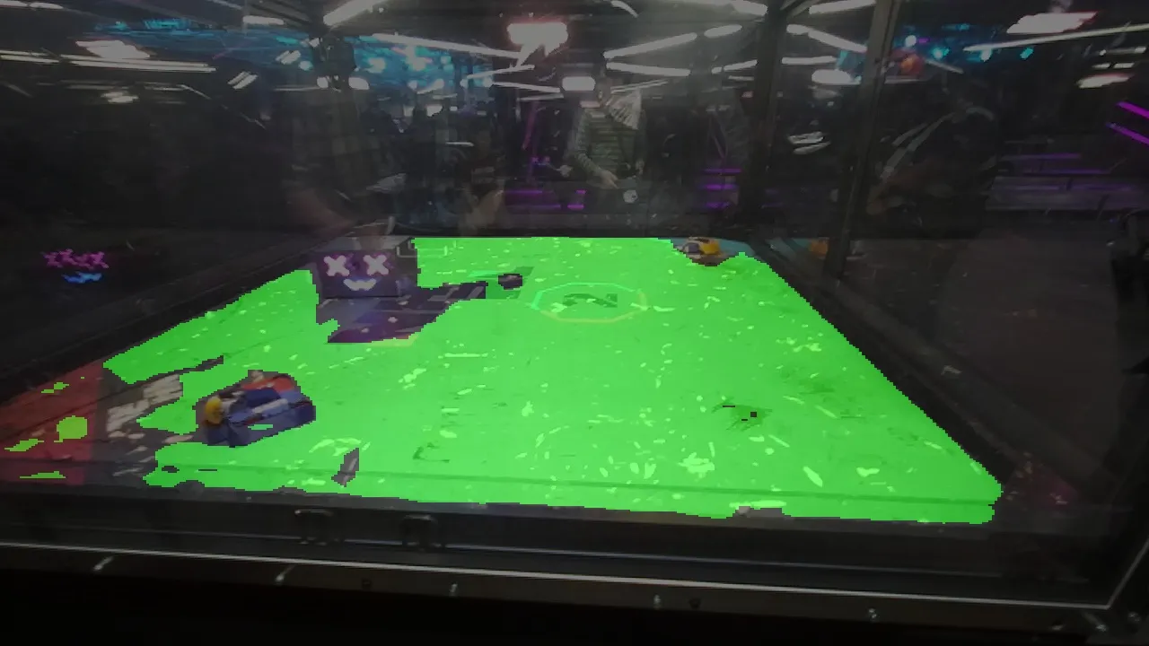
Green pixels represent the output of the model. It’s overlaid on top of the input RGB image. As you can see, the result is a bit patchy. Later filtering steps fill in the gaps.
The ZED 2i is a stereo camera, meaning it has two RGB sensors. With this information, it can compute depth at every pixel. The ZED 2i hardware isn’t particularly special besides having camera intrinsics stored on the device. The magic is the ZED SDK running on the Jetson. StereoLabs has developed what they call a neural depth model. Instead of using classical computer vision techniques, StereoLabs is using a neural net to convert stereo images to a depth image. The neural net learns how to produce high quality depth images. This approach produces smoother depth images where classical methods would produce noisy data or no data at all. I leverage this depth image to find the 3D plane of the field.
The field model outputs the mask and the ZED SDK produces a depth image. These two images get put through the following pipeline:
| Step | |
|---|---|
| DeepLabV3 mask output | 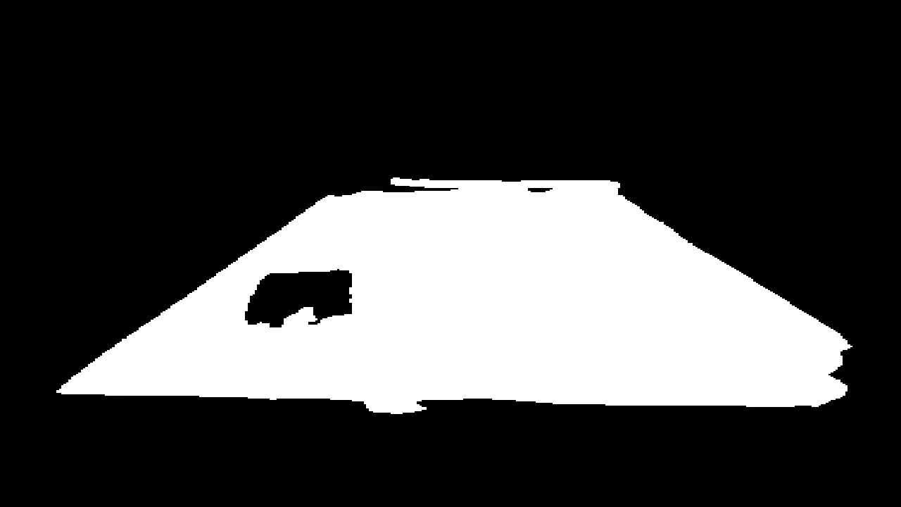 |
| Find largest blob contour | 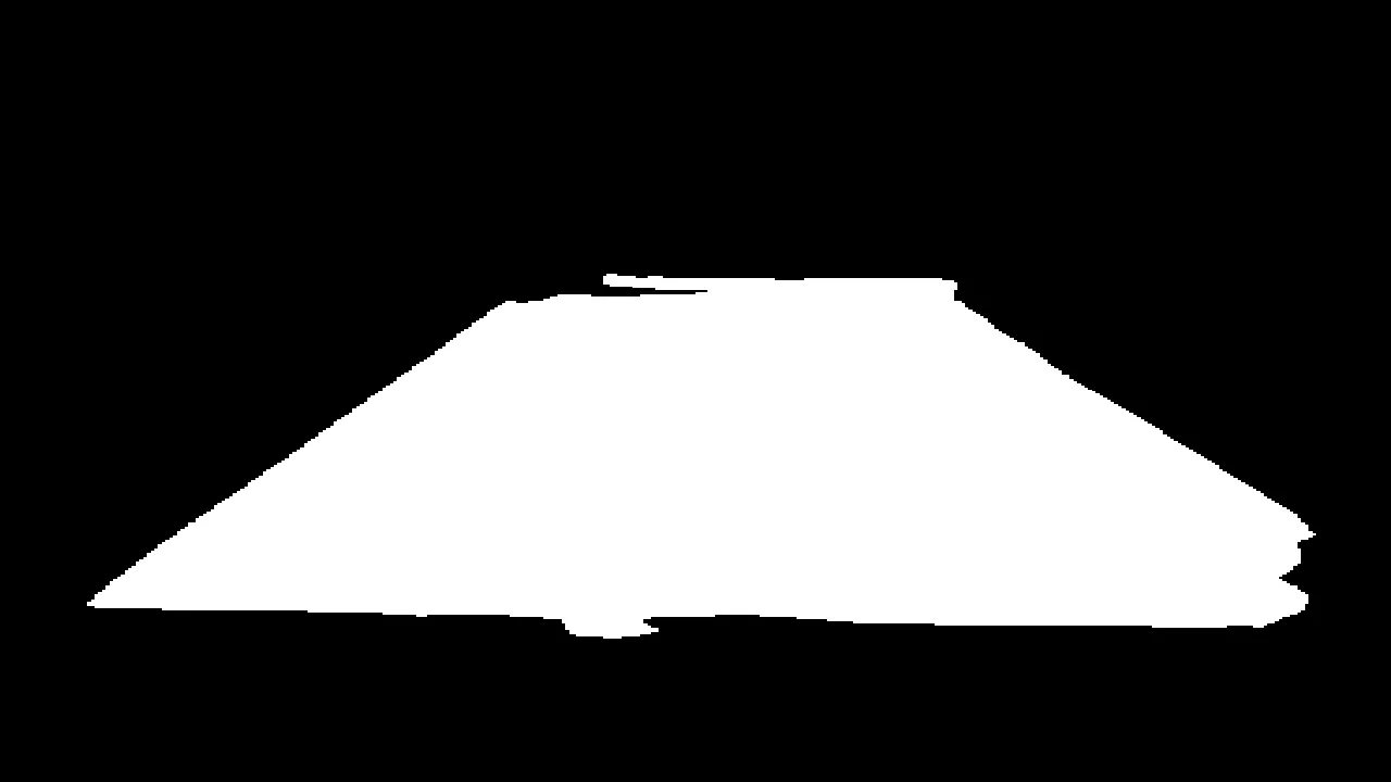 |
| Mask depth image | 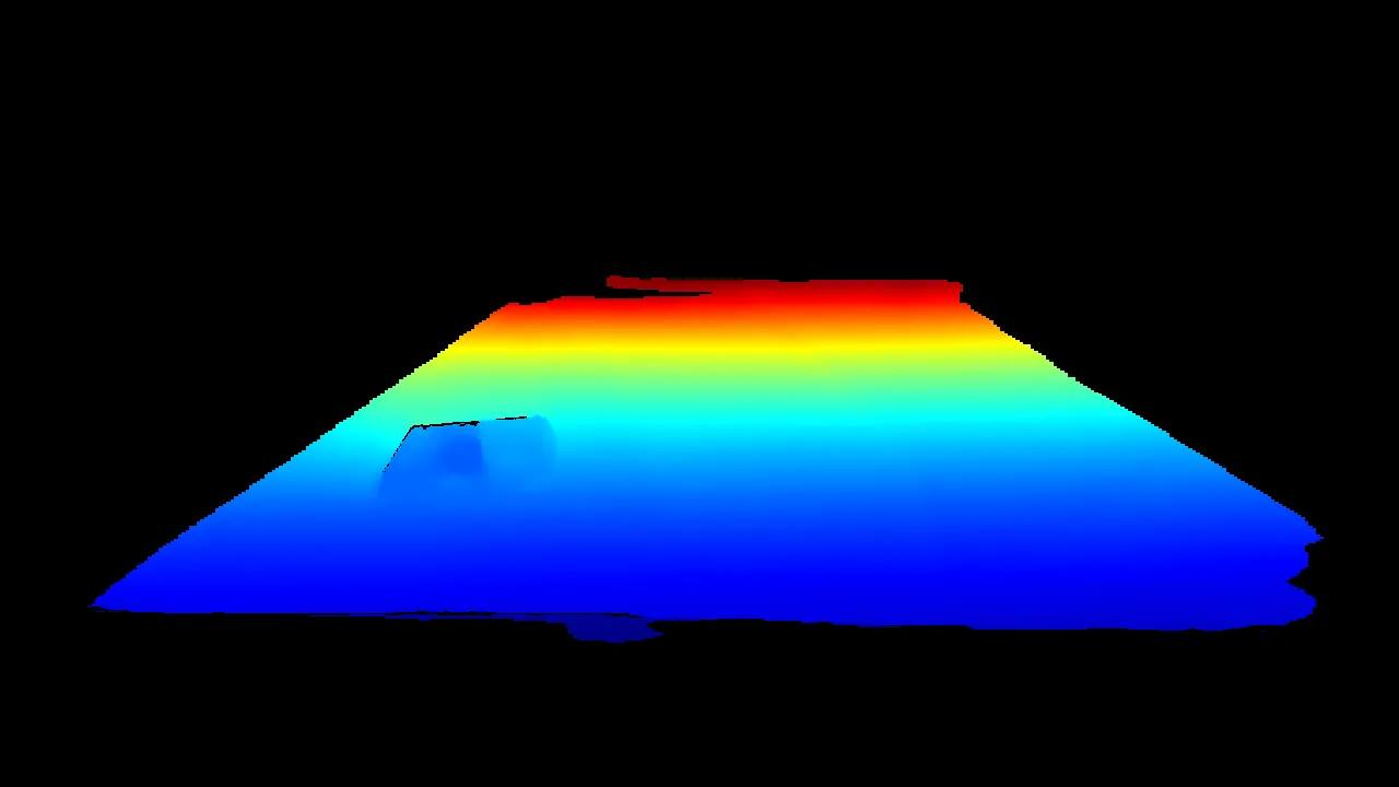 |
| Convert depth image to point cloud | 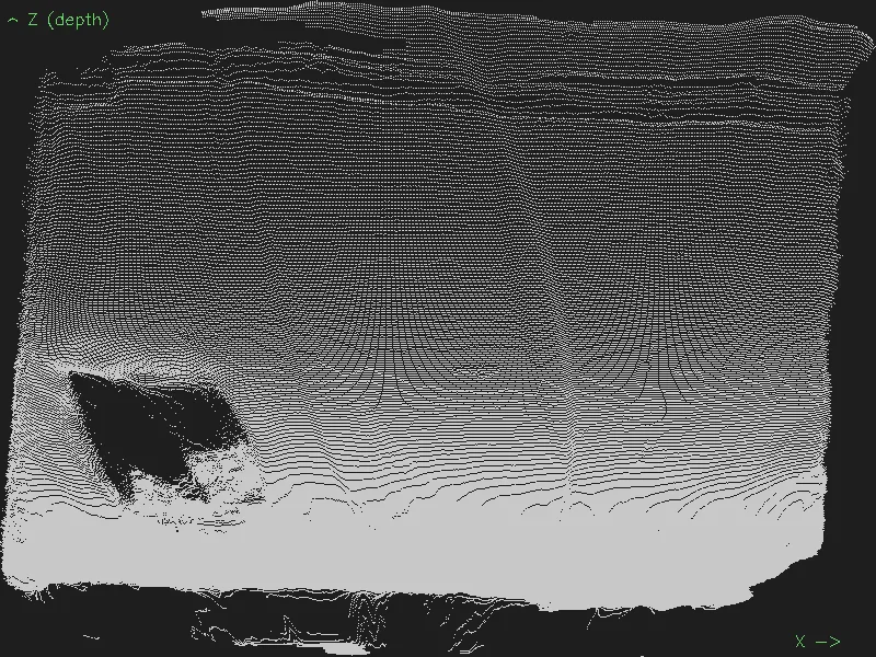 |
| RANSAC plane fit | 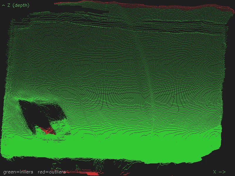 |
| Transform inlier cloud points so Z=0 (flatten cloud) | 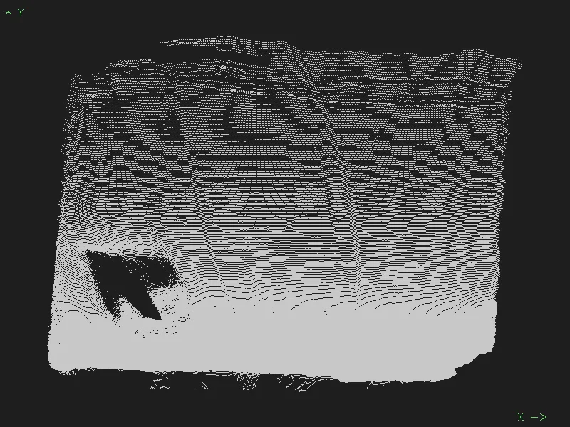 |
| Find minimum aligned rectangle | 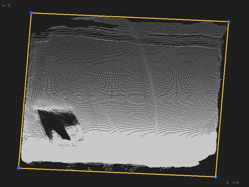 |
| Compute nearest edge angle | 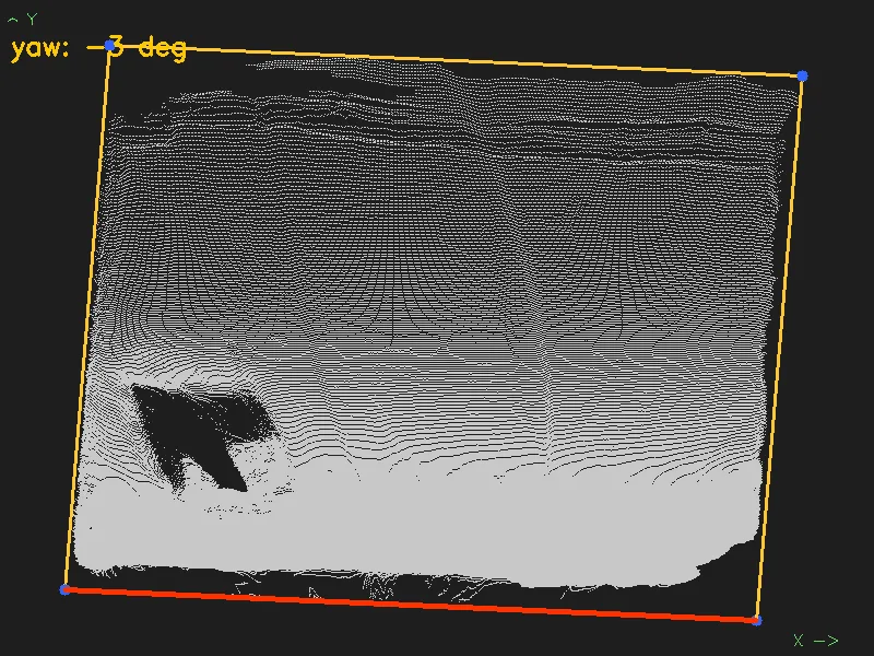 |
| Compute full 3D transform and transform from field center to camera | 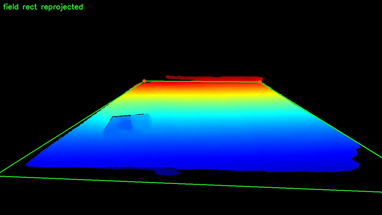 |
The depth image defines a distance away from the camera at each pixel. This can be converted to a point cloud using the camera’s intrinsics matrix.
The reason for the “Compute nearest edge angle” step is to establish the camera’s orientation with respect to the field. If I didn’t include this step, the field’s X axis would be aligned with the camera’s. This isn’t necessarily a problem, but it creates a consistent coordinate system across runs. Boundary checks become “am I within a width and length” instead of “am I inside this rotated rectangle”. Much easier to think about. This doesn’t establish an absolute x coordinate though. The x axis will point in one of 4 directions depending on which side of the cage I’m standing on. Not a problem for NHRL because after the fight starts, it doesn’t matter what side you’re on.
Camera motion tracking
This is a new addition for this competition. During our October 2024 event, it took us ~3-5 minutes to
- Setup the tripod
- Deploy the lawn chair and table
- Plug in the battery pack (the laptop would throttle its GPU without one)
- Plug in the transmitter
- Identify the field
- Start the recording
The program was also unreliable so a restart (or worse, a reboot) was required from time to time.
At the start of the day, the staff were forgiving. By the end of the day, they were pushing us to start on time. Our last fight of the day, the autonomy didn’t start until half way through the match!
To avoid this, I put all compute into a single, portable unit. No extra tripods or alignment. Just press a button and the system is calibrated. I could have done this by running our field model pipeline every frame. It takes around 30 ms for the pipeline to run on the jetson.
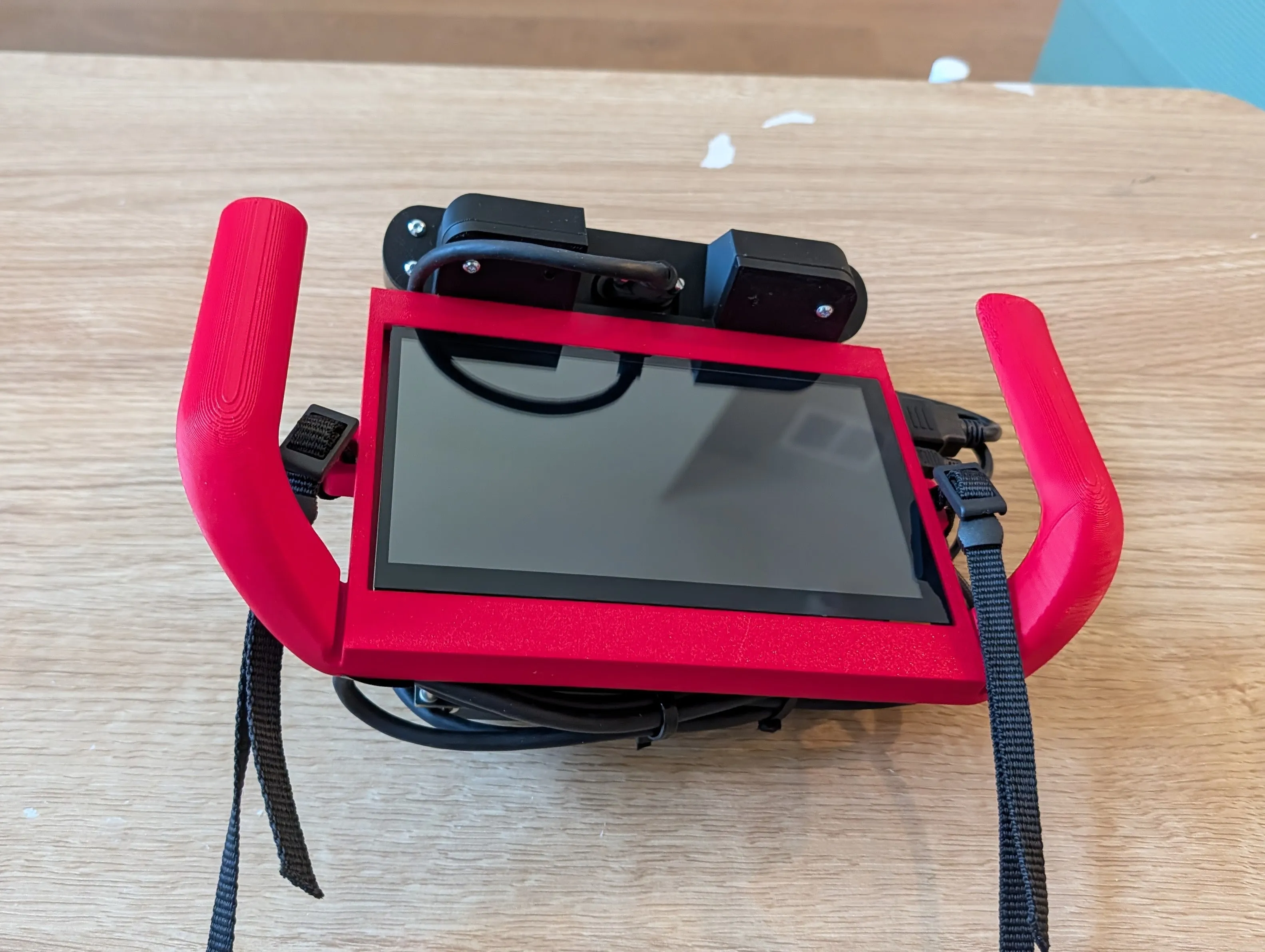
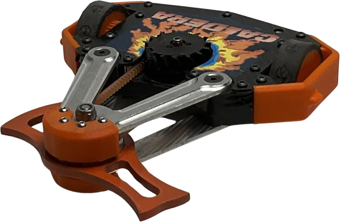
Here’s the hand-held autonomy device:
Latency
I budgeted 60 ms of latency for the system. Our robot moves at ~2 m/s top speed. In 60 ms, our robot moves 0.12 meters. The robot’s length is ~0.22 meters. Adding 30 ms of latency would translate to 0.18 meters. Latency can be compensated for in the control loop but with how unpredictably the robots move, I at least want the target to be comfortably within the robot’s footprint to have a chance at hitting them.
I could recover this latency by disabling depth computation but I need depth for the pipeline to work. If I want depth on a single frame, the ZED SDK requires you to close and reopen the camera to change this setting. In that time, the camera will have moved.
To work around this limitation, I utilized the ZED SDK’s visual SLAM feature. It combines the ZED’s built-in IMU and visual tracking to produce a 3D pose relative to where the camera started. So the strategy is this:
- Run the field model pipeline on RGB and depth data
- In a background thread, run the ZED SDK’s visual SLAM.
- Compute the transform from camera location at field initialize to the current pose
Using this combined transform, I can compute the field center to camera transform. Combined with the transform from the camera to the robot detection, I can get the robot’s pose relative to the field center.
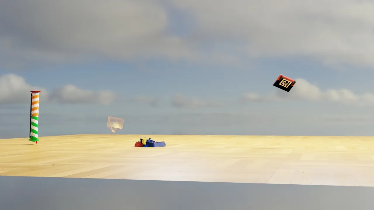
Combining everything
With all these pieces in place, this is the final output. Both robots and field are tracked.
Synthetic data generation
How did I get these models to recognize robots?
This was the biggest innovation of the project and the main reason for its success. Data curation is usually the biggest challenge of any AI project. For our prior events, I labeled 5000 images by hand. That means clicking the “front” and “back” keypoints of every robot in an image. 5000. Times. It took 6 months to collect this data. I need to recollect this data every time we do a visual overhaul/design change.
This was not sustainable.
The hot new technique in robots is synthetic data generation. Using tools like Isaac Sim or Blender, researchers have been able to train models using only simulation generated (synthetic) images. I chose Blender for this project. I went with this tool over Isaac Sim mostly because I’m too scared to learn Isaac Sim. I’ve worked with Nvidia’s tools for a long time. Dependency management is not Nvidia’s strong suit. From what I’ve seen Isaac Sim is just as messy and confusing. Blender can produce high quality renders and is well documented by the community.
I don’t know Blender. However, I found this tool called BlenderProc. It allows full control with Python scripts without needing to open the Blender application. This is great not only for animation but also because LLMs can code up a synthetic image generation tool for me. The source code for that is available here.
There are prerequisites to running the tool:
- Obtain robot CAD files. I export GLTF files directly from OnShape.
- Obtaining HDRIs (basically smart skybox images).
- Download textures. OnShape models don’t look realistic out of the box.
- Download distractor models.
- Edit the config to map the textures to colors on the OnShape model.
Sounds simple, but working through bugs was tricky. I spent a lot of time getting the robot’s random orientation to look reasonable. I had the AI implement a system to reshuffle the scene if the robot was mostly blocked. However this didn’t work all the time for some reason, especially when new distractor objects were loaded into memory. I ended up just putting in a failsafe that says “if the robot should be visible and isn’t, discard the render”.
The output of the synthetic image generator is RGB images paired with YOLO annotation text files. I had the AI implement keypoints and instance segmentation modes. Here are some of my favorite images it generated:
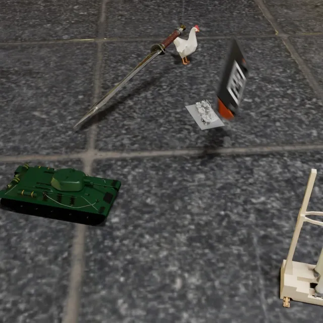 |  |
 |  |
I generated 34945 images for the keypoints model and 18922 images for the instance segmentation model. The models performed well even just with pure synthetic images. To boost performance, I still labeled 499 images by hand. But much better than 5000. Also since I was only labeling Mrs Buff, I could label much faster. It took me 3, 1 hour sessions to label the 499 images by hand.
I tried using CoTracker to automatically propagate manually labeled images in a video. However, I discovered it struggles when the robot turns. So I dropped this idea for now.
Labeling other robots
I’ve been mentioning that I trained an instance segmentation model. This was for the opponent robots. I decided for this project I didn’t care about the opponent’s orientation. We would just target their center. Going forward, I’ll eventually need to figure out the opponent’s “danger area” and avoid it. But for now, this was enough work.
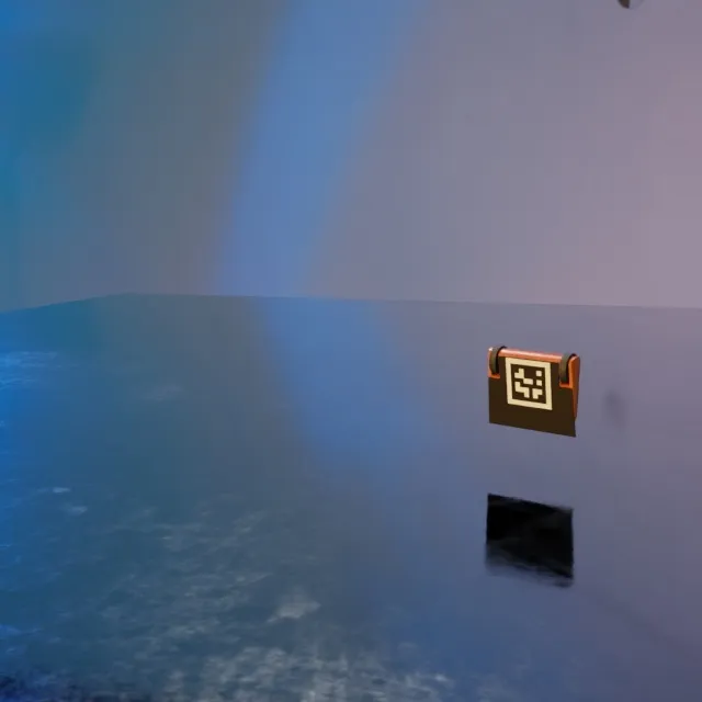
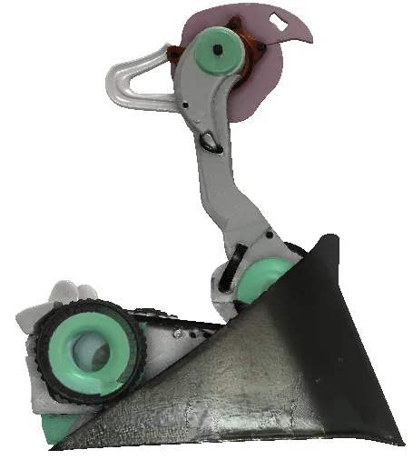
I did generate synthetic images for this training set, but they aren’t very realistic. I don’t have high quality CAD files like I do for Mrs Buff. I used a tool called meshy.ai to create reasonable looking models from single images. Here’s an example:
| Synthetic | Source image |
|---|---|
 |  |
This one looks great. However, being locked to a single image means meshy messes up the perspective sometimes. There’s no language input or opportunity to correct the model. This robot, for instance, doesn’t have its wheels on the ground:
| Synthetic | Source image |
|---|---|
 | 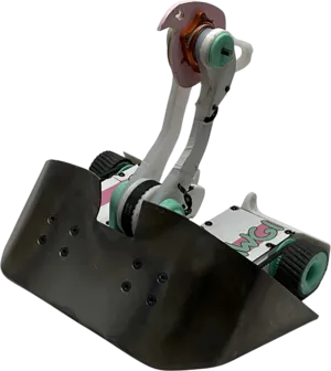 |
This likely is good enough for training, but I knew in order for the model to generalize on what an NHRL robot looks like, I need lots of labeled data. Luckily, NHRL does this cool thing where they record every fight ever and upload the raw footage to brettzone.nhrl.io. I just need a way to label it.
After searching around, I discovered video propagation. It’s possible to label a single image and propagate the label to the rest of the video. One example is SAM 2. I tried it and was impressed. Then, Samurai was released which promised even better video propagation. I started to try it but got distracted by work.
SAM 3 was released in November 2025. When I returned to the project, I gave it a try. You can prompt it with text and the model will attempt to find your object in the video. That feature didn’t work well for NHRL robots, so I stuck with the video propagation feature from manual labels.
Building a tool to label robots
This was a project unto itself. I built a custom labeling tool that can run on a GPU cluster. Check out the project here: https://github.com/Woz4tetra/SegmentFlow/. This tool can store and manage videos as they move through the labeling lifecycle.
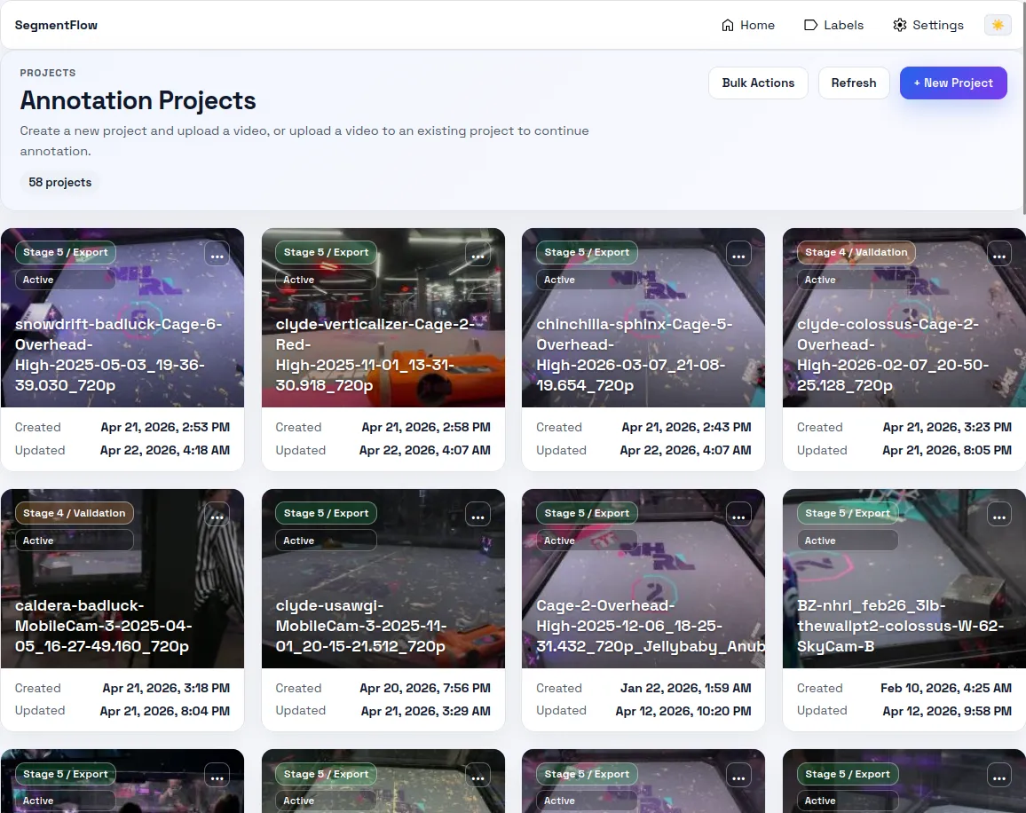
It was 100% vibe-coded and it shows. I don’t know how to build a web application and wasn’t as interested in learning for this project. If I were to do it again, I would set up a good remote desktop connection to the GPU cluster and build a Python based data labeler.
A video has the following lifecycle:
flowchart TD
    S0("Stage 0\nVideo upload")
    S1("Stage 1\nTrim")
    S2("Stage 2\nManual labeling")
    S3("Stage 3\nPropagation")
    S4("Stage 4\nValidation")
    S5("Stage 5\nExport")

    S0 --> S1 --> S2 --> S3 --> S4 --> S5
Video upload can come from local files or from BrettZone directly.
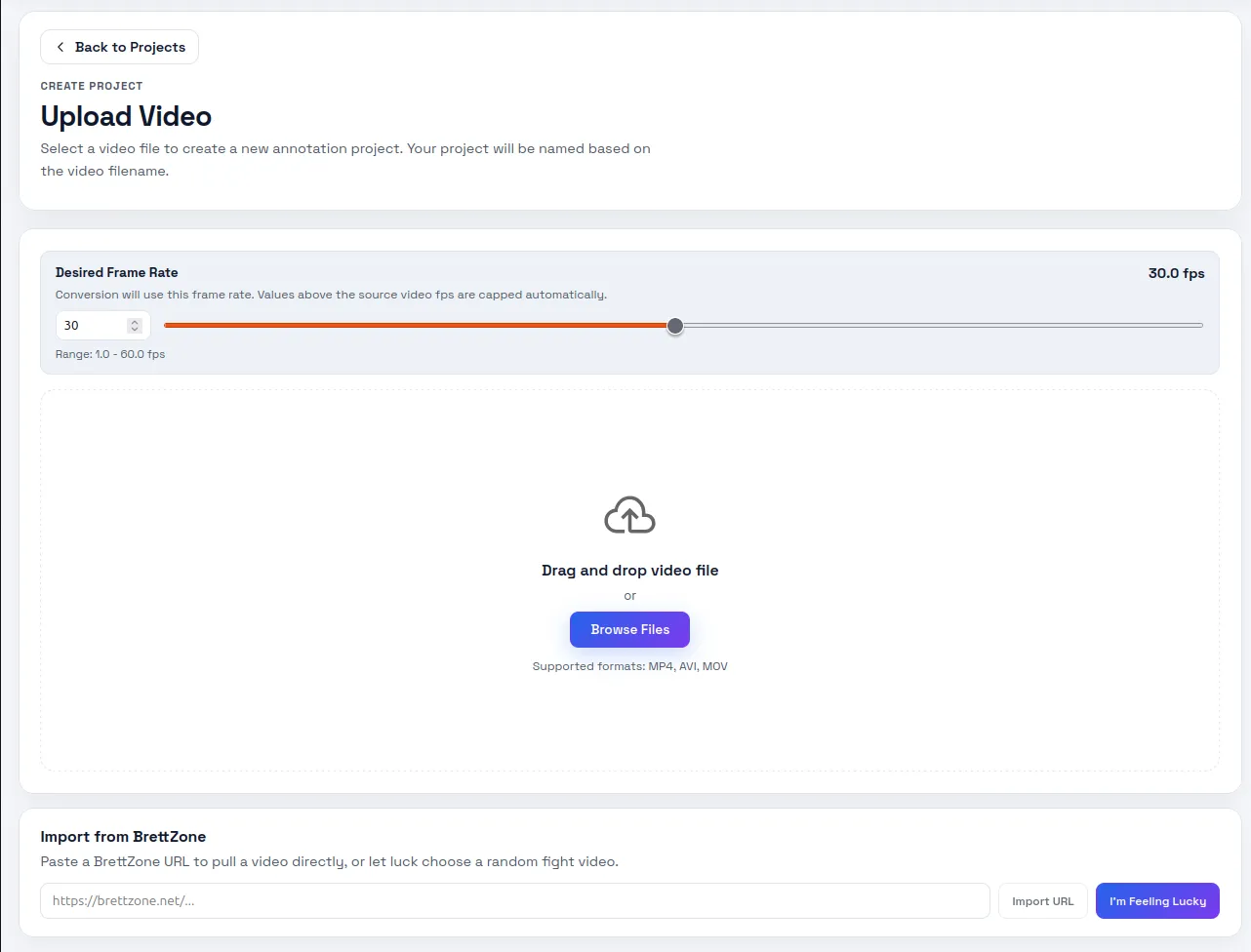
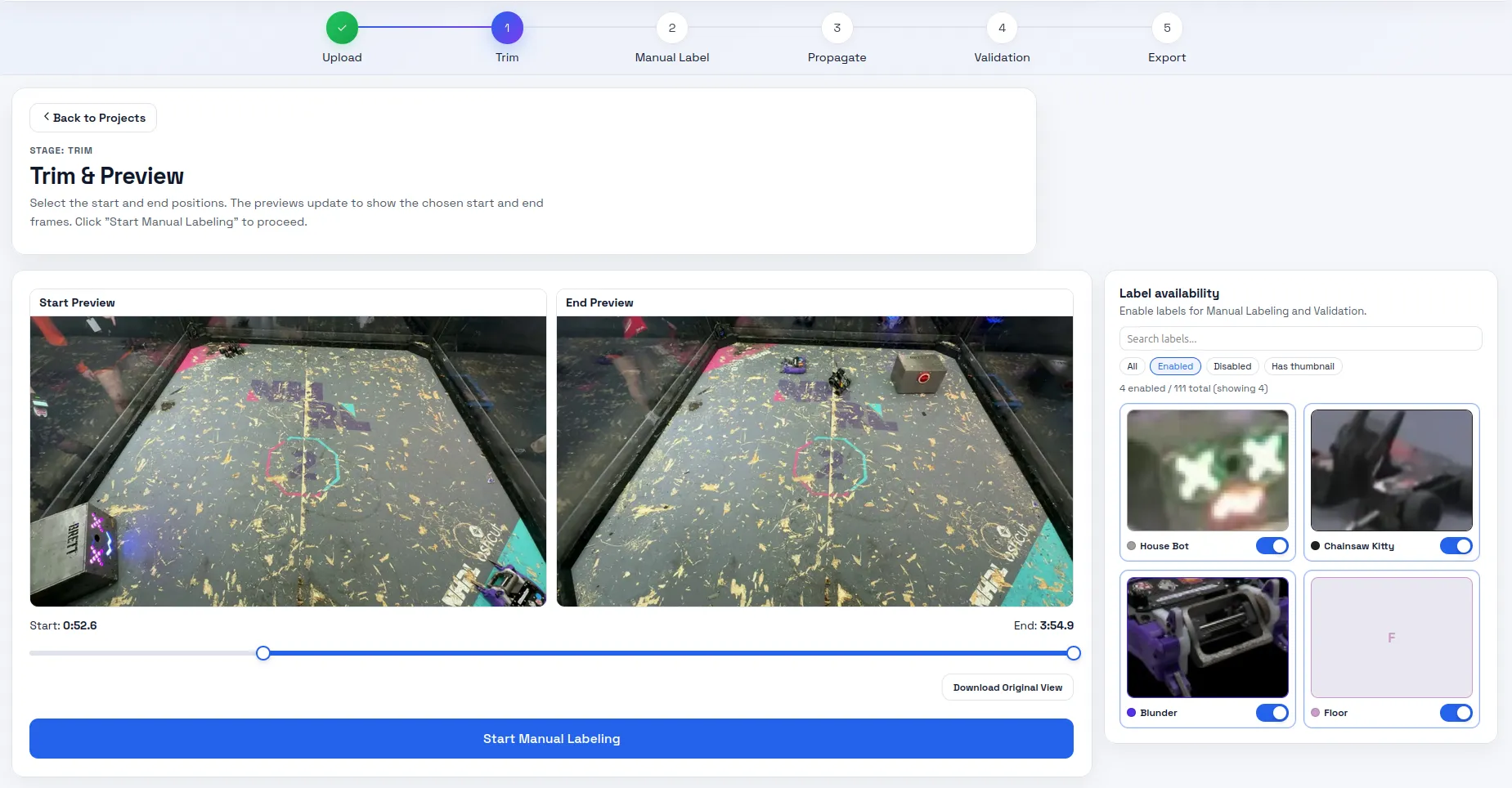
Once the video is uploaded and converted to images, the project transitions to the Trim stage. I select which labels are present in the video. If using a BrettZone link, the tool automatically pulls the robot name and thumbnail from the website. For files on my machine I add labels manually in the Labels screen.
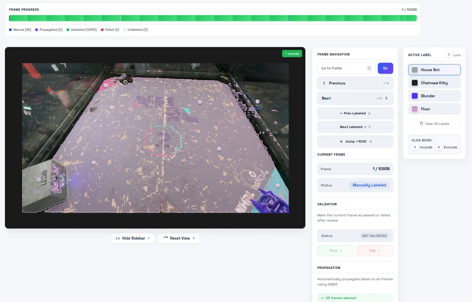
Then I do the most laborious part and the screen subject to the most bugs: labeling. To label an image, I click points on the image that correspond to each label. I don’t want to draw the boundaries by hand, so I call SAM 3’s point prompt API to generate the segmentation for this image. Getting the server and the client to sync up properly was a nightmare. The AI put in a lot of extra websocket bloat to keep the preview mask and the actual mask in sync. If I requested any change the whole pipeline would break. There’s still a few visual glitches but for now it’s stable in the backend.
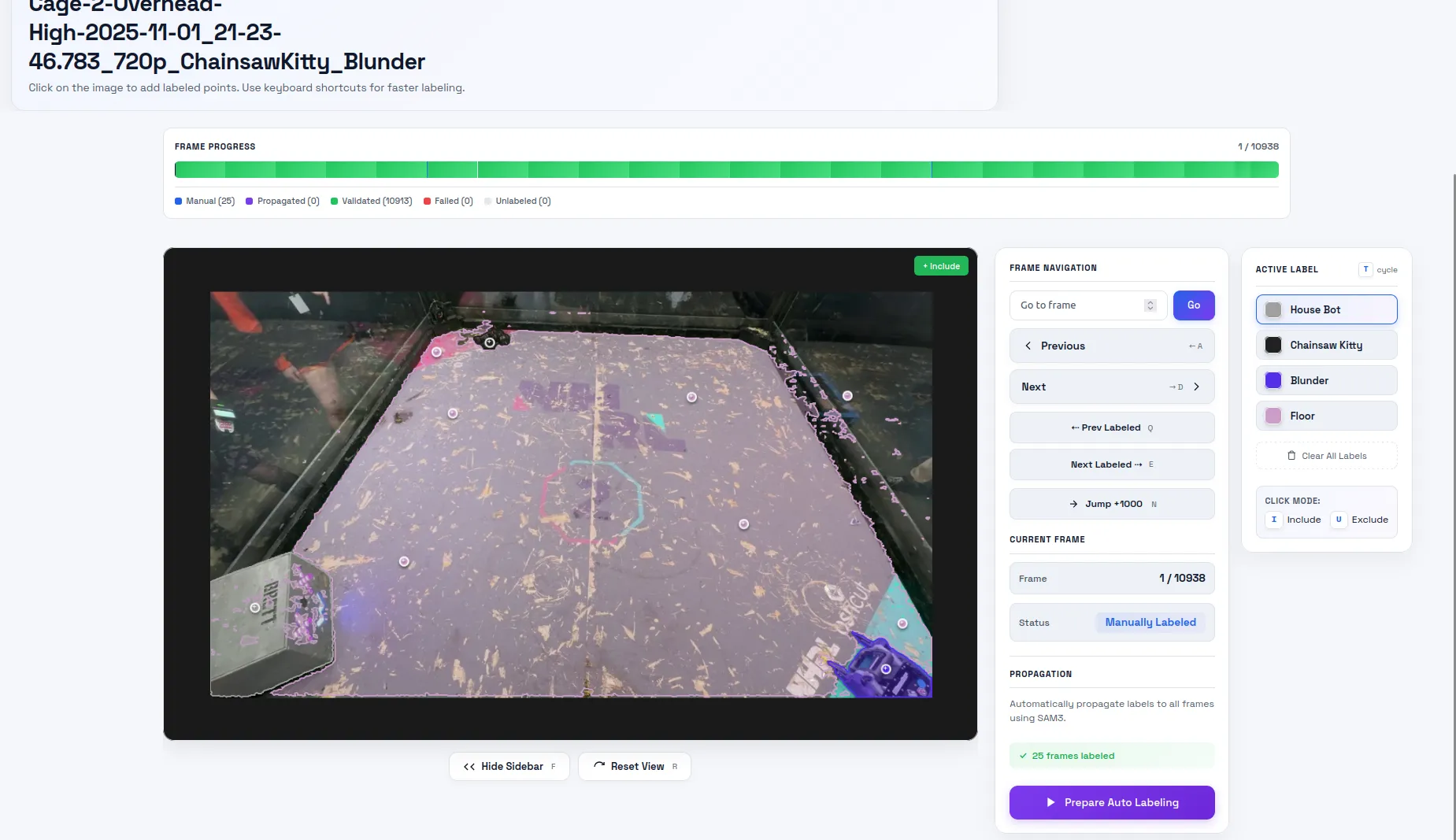
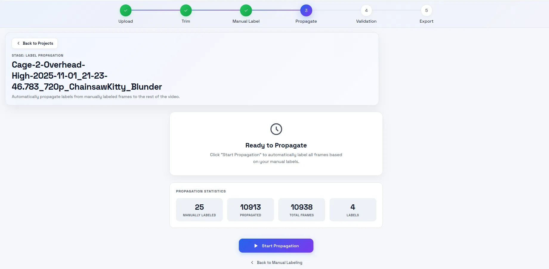
Now the fun part: propagation. This takes the manual labels and fills in the gaps. I set the propagation length to 1000. Past this limit, I found the model would forget about the object, especially in the mobile cam videos. On my cluster of 3 A6000 GPUs, it takes ~5 minutes to propagate 1000 images.
The next stage is my least favorite: validation. I want to flag images that failed propagation, manually label them, and repropagate. If I see that a frame failed propagation, I mark it as fail and all the images up to the next manually labeled image are marked for repropagation. Towards the end of the project, I wouldn’t bother repropagating because it took a long time and would mark them so that they don’t get downloaded in the export step.
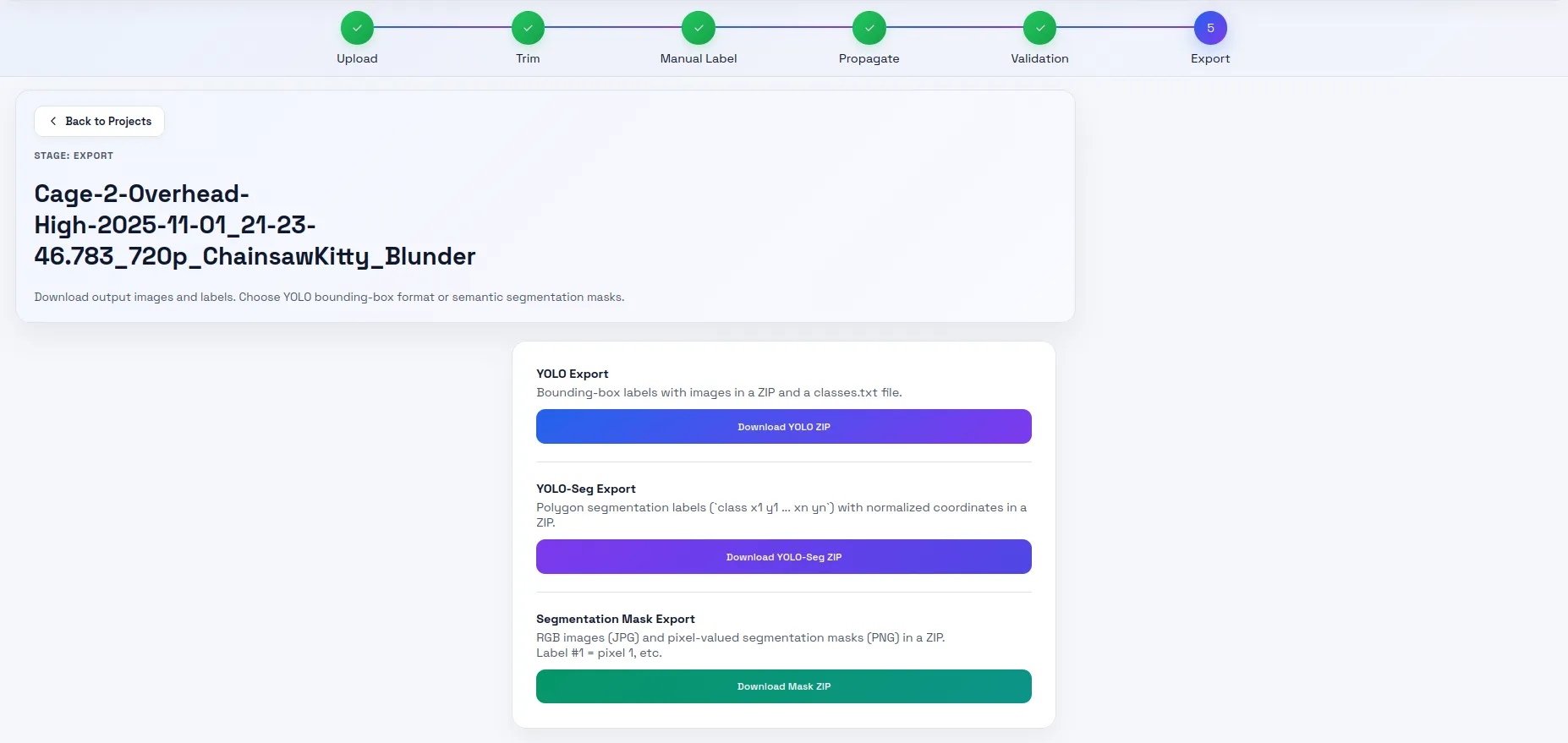
This step converts the database to a zip file of images and corresponding labels. I used the YOLO-Seg format.
Training
This step was simple. I run the training script which is a tiny wrapper around Ultralytic’s YOLO.train function. I give it the model I want to train, point it to the dataset directory, and then wait for a few days.
yolo26n-pose can do 500 epochs in 12 hours. yolo26n-seg took ~3 days to complete 500 epochs.
I also train the DeepLabV3 model. It achieves the best performance after ~50 epochs. This takes ~1 hour.
I take the output of the model, convert to TensorRT engine files (once for my x86 laptop, once for the jetson), and then the application is ready to run. Converting to engine files on the Jetson takes a surprisingly long time. About 10 minutes per model.
No hardware
The software was ready to test a little before the proper hardware. I had AI generate a simulator for me. I used Unity in prior attempts. However, that software was becoming difficult to maintain because of the way I set up the scripting. Adding a new robot was a process of trial and error. Its main functions were full stack integration testing and synthetic image generation.
I decided to try Genesis this time. They advertise it’s designed for robotics. It is definitely more AI agentic coding friendly being programmable completely in python. I didn’t need the synthetic data generation since Blender covered that. I wanted it for integration tests. Ideally, I would tune the PID controller in simulation before trying it on the robot.
However, I found the physics to be not very accurate. I punched in the same inertial values the Unity project and the robot did not behave correctly. Usually it would jump and bounce into infinity. I managed to tame it enough to get results I could work with, but the values I used for the PID were not at all the same as the real robot. I will revisit this component another day.
Crossfire integration
We used a Radiomaster TX16S with a TBS Crossfire Micro TX module. It has been very reliable. However, the 20 ms latency penalty is of concern. In future competitions, we may switch to a 2.4 GHz protocol. We tried WiFi at our first event and that was a mistake. NHRL has a lot of guests with phones. Another 2.4 GHz protocol may work just fine though.
The main hardware interfacing layer to robot is the OpenTX transmitter. If we were to unplug the handheld autonomy device from the transmitter, our robot would behave the same as any other NHRL robot. That is, completely manual. This is by design. We wanted a way to reliably disengage autonomy in case something went wrong and we weren’t able to control the robot. It’s an NHRL requirement that the system fail safe.
To do this, we leveraged OpenTX’s trainer mode. Normally, you can plug two OpenTX transmitters together and one
will act as the “trainer” and the other the “student”. In my case, I modified OpenTX so the “student” can receive
commands from the USB serial connection.
Check out all the changes I made here.
When trainer mode is activated (configured to activate via a switch in the mixer settings), trainer values
set by the serial command trainer <channel> <value> will be sent through the mixer. Using this stream,
I can even send back telemetry from the Crossfire protocol. Mr Stabs MK2 sends back IMU data for instance.
It’s not useful for realtime feedback though. CRSF (the wireless serial protocol developed by TBS) limits
IMU data to 5 Hz. This is not configurable.
Mrs Buff MK3 doesn’t utilize any telemetry. All sensory feedback is done through the camera.
Other useful changes to config and OpenTX are:
- I made the default USB mode “USB Serial (CDC)” so the Jetson could communicate with the transmitter.
- Channel streaming back over USB serial. I can see when we enter auto mode this way.
- Set all trainer inputs to zero when the trainer signal is lost.
- Docker builds for creating firmware binaries.
Failsafe reliability
I attempted to use a microcontroller on Mr Stabs MK2. For the October 2024 event, I used the Matek F405-miniTE 20x20. It worked well except for one of our fights. The robot took a big hit and then spun in place uncontrollably. This is an unacceptable failure mode. If this robot had an active weapon, we would’ve had to wait until the battery died before pulling it out.
Over the winter, I tried using an ESP-32 instead. However in tests at home, it had the same issue! After a while we concluded that the reset button was likely getting pressed during big impacts. It’s the reason we used screwed-on power switches for Mrs Buff. However, we decided telemetry didn’t add much value with the crossfire protocol anyway so it wasn’t worth adding a microcontroller to Mrs Buff MK3. We know this system works from prior competitions.
Drive tuning
We use AM32 ESCs on Mrs Buff MK3. For this competition, we did not tune these ESCs at all. It’s one reason they’re popular at NHRL. However, I noticed the dead zone is not even. The motor might start moving at +20, but -10 in the opposite direction. This means the robot takes off at an angle. I compensated in software by using a “lift off” dead zone. Numbers less than a small dead zone get mapped to zero, but numbers above a higher threshold get bumped above the hardware dead zone and scaled linearly. This largely fixed the issues but I think in future, we’ll want to optimize these drives.
Software bugs
This is my first C++ project in a non-ROS environment. AI did the bulk of the coding, but I did review every line before the competition (and found some very silly design issues and potential bugs).
There were bugs leading up to the competition. These were some notable ones:
Covering one of the ZED camera lens
I put in a system to reopen the camera if the connection fails or if no frames. USB is flaky so this could happen from time to time. However, I found that when I set the camera down on a table, the application would crash. Turned out I wasn’t closing the camera properly, so it kept trying to reopen and not succeeding. It would do that over and over rapidly until the system ran out of memory and the Jetson would crash or kernel panic. The fix is to not attempt to reopen the camera for certain faults and not crash the application when frames don’t arrive for a while. I decided in this event it would be better to reboot the system since it takes a similar amount of time to cooldown and reconnect to the camera (~40 seconds).
I used AI to identify the kernel panic and other OOM issues. These lead me to isolate the ZED USB issues.
Yaw conversion
I noticed in simulation the robot’s angular command would oscillate wildly when facing 90 degrees to the opponent.
I had the AI implement a ground truth passthrough to remove the model as a source of error. The AI ended up failing
to find the bug. After a while, I had a feeling it was a math bug because the jump would happen at these
specific 90 degree angles. My intuition was correct. As soon as I pointed this out, the AI immediately found
Eigen’s eulerAngles method was to blame. It was constraining yaw to 0..pi instead of -pi..pi.
I was using it to convert 3D poses from the camera to 2D poses for navigation computation. The AI implemented
an alternative method using atan2 and the issue went away.
How autonomous was this system?
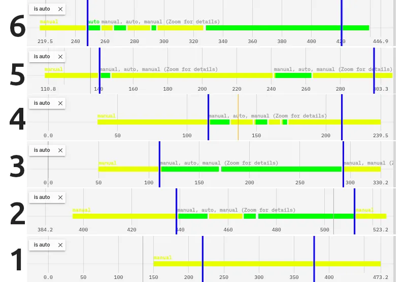
Here’s our fights represented by how long the autonomy was on for. Green being autonomy on, yellow autonomy off.
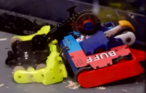
Fight 1 was against Clyde. We got melted. Photos at the end of this blog.
Fights 2 and 3 Mrs Buff was upright the entire fight. That’s when Aidan felt comfortable letting it run free.
Fight 4, the opponent got high centered on its own bent piece of metal. Aidan had our robot hang back while they got unstuck.
Fight 5, we spent most of it with a hammer saw embedded in our chassis.
Fight 6, John Undercutter wacked us so hard we flipped over. Aidan spent most of the time he had all his wheels trying to get the robot back upright.
So for fights where the robot had control, we were over 80% autonomous! This isn’t a perfect metric though. Aidan was still helping on the sticks. When the robot was pinning, he pushed full throttle since the code isn’t set to drive the robot at max linear speed. If it was getting stuck on a wall, he would help.
Despite this, he said it was useful. From my observations, he got way more hits on the opponent than before. The autonomy was relentless in chasing down opponents and was great at pointing the weapon towards the opponent. These are the basic principles of a great NHRL driver and tough to do well under pressure.
We made it to one round before the quarterfinals and scored 9th in the tournament out of 78 robots.
What’s next?
I think this repository is a great foundation to build off of. It’s performant enough to serve as a steering assist. Aidan really enjoys this as a feature. Driving at NHRL is fun and I don’t want to take that away from him. I think a truly interesting pursuit is how can autonomy augment human capability.
Hammer saws
These robots have a spinning or static blade on an arm. It swings down rapidly, stabbing into delicate electronics and batteries. They’ve been gaining in popularity because most teams use reinforced plastic top shells since the sides have armor plating. These hammer saws smash through the weaker top plates.
The problem with them is it’s very hard to fire them at the right time. Most of the time they hit nothing or miss the robot weak points. Our robot was a prime target. However, “Sting Operation” missed our battery by millimeters and lost the fight because their drive became nonfunctional. Very lucky for us.
If our perception system could identify opponent weaknesses, it could in theory fire the hammer at exactly the right time.
Better control
I did no latency compensation and no path planning. Just a simple PID to the target. Now that the perception system is showing signs of robustness, I would want to show that we can predict where the opponent will be and drive towards that.
We also kept overshooting our target a lot and hitting the wall. I think this is partially due to untuned ESCs and lots of friction on Mrs Buff, but it’s also likely because of latency. I will want to revamp the simulation to decrease iteration time on this front.
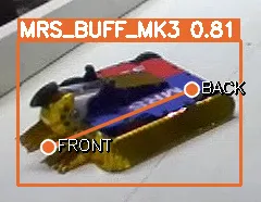
Better identification of opponents
I had 5 label classes for the opponent segmentation model: robot, object, house bot, Mrs Buff MK3, Mr Stabs MK2. I found the model would think some robots were Mrs Buff for no apparent reason. Robots I thought looked similar to Mrs Buff the model had no trouble identifying as an opponent. Fight 2 for instance, we fought a red robot but it doesn’t look like Mrs Buff. And yet every few frames it would mislabel it and targeting would be dropped for a few frames.
I think to address this, I need to introduce more types of robots to the dataset. Video propagation is good but that doesn’t automatically expand to novel robots. I still have to label a lot of new videos. Synthetic data worked very well for Mrs Buff’s keypoint model. I’m thinking of using meshy.ai to generate tons of NHRL robot models and generating a synthetic data set from that. This would allow me to eliminate the segmentation model and even add things like “weapon” or “weak point”.
Damaged robots
We lost a wheel in our last fight of the day. That’s inevitable when you’re up against a well matched opponent. I would like to identify this damage and activate alternative control methods. I could toggle these as I identify damage, but driving with one motor is still tough.
Self-righting
Mrs Buff is difficult to self-right. I think this would be a great auto routine to implement. There’s a specific sequence of moves required and it’s tricky to do them under the pressure of battle. We likely need to add a faster rate data stream for IMU to make this work.
Flame robots
Clyde cooked us in our first match of the day.
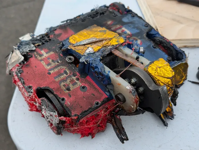
During the fight it looked like our robot was thrown into a camp fire. To our camera though, it looked like Clyde had summoned a small sun. It was completely blinded. Now that Clyde has figured out its winning strategy (they won the tournament that day), I think there will be more flame bots around. We’ll have to look into IR cameras or other ways of defeating flame bots quickly.
Model verification
I want a way to automatically assess model performance. So far, I’ve been running models on unlabeled video and getting a vibe if it’s better or worse. With these huge leaps of improvement thanks to synthetic data, I’ve gotten away with that. But now as I fine tune the models I need a way to tell on a chart if this model is going to perform better on novel data.
One reason it’s been tough is because I’ve had so little data that any new video immediately gets fed in as training data. Now that I have synthetic data, I can rely on real video less for training and more for verification.
I want to run experiments like “if I separate each robot out by name will that perform better than lumping them into one category of robot?” or “how reliable if labeling the weapon of robots?” With verification tools, these questions can have concrete answers.
Conclusion
I would rate this event as a success. I found a successful strategy for identifying our robot and the opponents and providing a tangible improvement to our driving performance.
A recap of our original objectives:
- Make 1 robot that kicks ass (as opposed to focusing on multi-bot)
- We, in fact, made a kick ass robot.
- Augment Aidan’s driving with autonomy
- The autonomy improved his aiming and got us more hits
- The simple control scheme allowed Aidan to smoothly take over if needed
- Participate in the May 2026 event
- We made it
Going forward, I want to find more ways to improve Aidan’s driving with autonomy and improving the perception system.
Stay tuned!